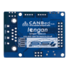

CANBed V1.3 Arduino (帶有CAN-BUS的ATmega32U開發板) MCP2515/MCP2551
NT$900 NT$800 未稅
CANBed-Arduino CAN-BUS 開發套件,搭載ATmega32U4晶片和MCP2515、MCP2551 CAN-BUS控制器和收發器,在單板上實現CAN-BUS通訊協議,無需其他MCU控制,本身就是一塊CAN-BUS開發板!
尚有庫存
- 詳細資訊
商品說明
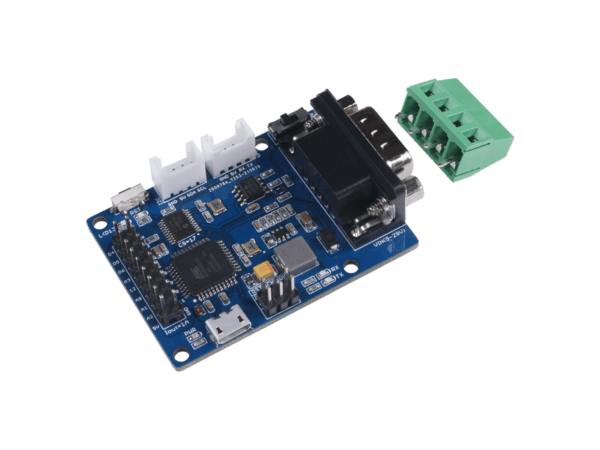
CANBed – Arduino CAN-BUS 開發套件內嵌了 ATmega32U4 晶片,這意味著您不需要在另一個 Arduino 板上添加其他跳線,它是一塊Arduino開發板本身加上 MCP2515 CAN 總線控制器和 MCP2551 CAN 總線收發器!CAN-BUS是一種通用協議,因其傳輸距離遠、通信速度中等、可靠性高而在工業中得到廣泛應用。現在你可以通過這個小小的開發板實現一個 CAN-BUS 項目。由於板載 ATmega32U4 晶片,該板的管腳資源豐富。事實上,板上基於核心晶片設置的引腳有18個,包括數字引腳、模擬引腳、UART和I2C接口。此外,該CANBed採用帶SPI接口的 MCP2515 CAN 總線控制器和 MCP2551 來實現 CAN-Bus 能力。還有兩種CAN總線接口可滿足各種需求,即sub-D9連接器和接線端子接口。它們將滿足您在連接方法中的所有需求。這款 CAN-Bus 開發板與 Arduino IDE 完美相容。借助 Arduino CAN-Bus 庫,您將為 CAN 項目節省大量時間。
CANBed-Arduino 開發套件 特徵
- 板上帶有 Arduino Leonardo 引導加載程序的 ATmega32U4
- MCP2515 CAN 總線控制器和 MCP2551 CAN 總線收發器
- 在 sub-D 連接器上可選擇 OBD-II 和 CAN 標準引腳
- 相容於Arduino IDE
CANBed-Arduino 開發套件 應用
- 破解和升級你的車
- 車輛動態控制系統
- 姿態和軌道控制系統
CANBed-Arduino 開發套件 規格
| Parameter | Value |
|---|---|
| MCU | ATmega32U4(with Arduino Leonardo bootloader) |
| Clock Speed | 16MHz |
| Flash Memory | 32KB |
| SRAM | 2.5KB |
| EEPROM | 1KB |
| Operate Voltage(CAN-BUS) | 9-28V |
| Operate Voltage (MicoUSB) | 5V |
| Input Interface | sub-D |
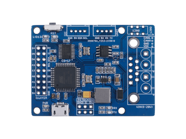
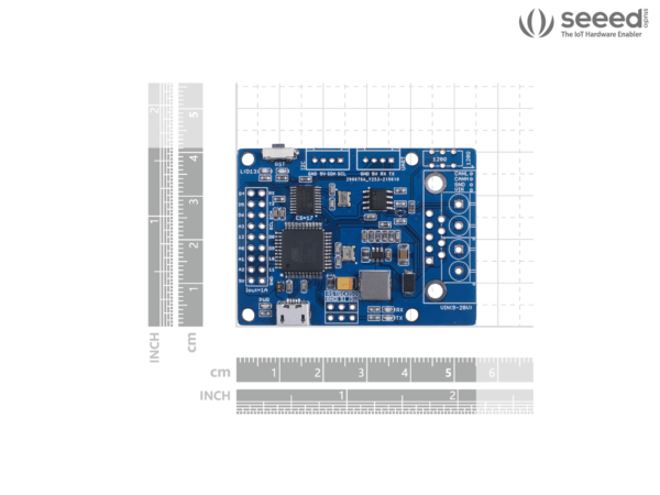
硬件概述

- 9×2 IO 引腳輸出:Atmega32U4 的 IO 列在這裡
- ATmega32U4:整個模組的主控主要用於在TF卡上存儲數據或通過C型線將數據傳輸到電腦上。 由於它是Arduino相容的,你可以用它來實現一些簡單的控制,比如當速度超過一定值時觸發蜂鳴器報警。
A:重置按鈕:重置板載 Atmega 晶片。 - 用於編程的Micro USB連接器
- ICSP Header 用於上傳引導加載程序
- CAN RX/TX指示燈
- sub-D連接器或CAN總線終端
D-Sub CANbus 引腳輸出
| pin# | Signal names | Signal Description |
|---|---|---|
| 1 | Reserved | Upgrade Path |
| 2 | CAN_L | Dominant Low |
| 3 | CAN_GND | Ground |
| 4 | Reserved | Upgrade Path |
| 5 | CAN_SHLD | Shield, Optional |
| 6 | GND | Ground, Optional |
| 7 | CAN_H | Dominant High |
| 8 | Reserved | Upgrade Path |
| 9 | CAN_V+ | Power, Optional |
-
- CAN總線120Ω終端電阻開關

如果你在 CAN 總線的末端使用這個端子,你需要在兩個焊盤之間焊接一個 120Ω 的電阻器,如果沒有就不需理會。
- 用於UART的Grove連接器
- I2C 的 Grove 連接器
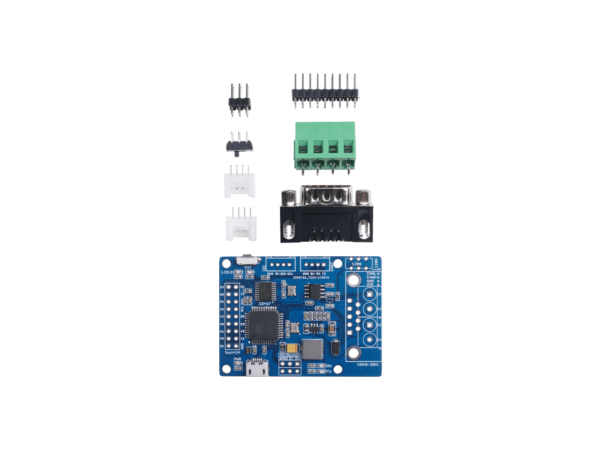
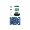
出貨清單
- CANBed PCBA (裸板,端子接頭需自焊)
- sub-D connector
- 4PIN Terminal
- 4PIN 2.0 Connector x 2
- 9×2 2.54 Header x 1
- 3×2 2.54 Header x 1
Documents
相關商品
-
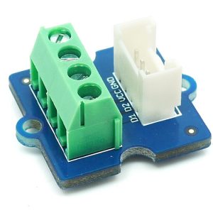
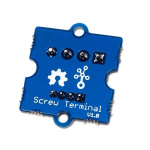
Grove – Screw Terminal 4P 螺絲端子座 額定功率可達 125V@6A seeed
Grove – Screw Terminal 4P 螺絲端子座有四個 3.5mm 端口座可達125V @ 6A。終端可以接受30〜20AWG線。這是最常見的螺距螺紋端子。Grove – Screw Terminal 有四個端口,包括GND,VCC和另外兩個未限定端口。
NT$100NT$80 未稅 -
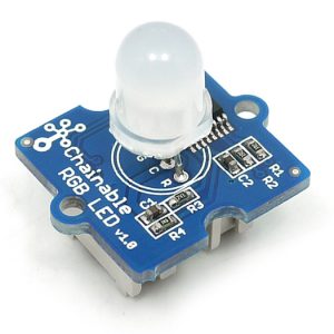
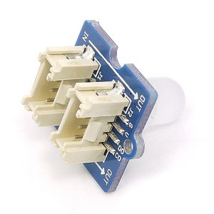
Grove – Chainable RGB LED 全彩 RGB 可串接式 LED 模組
Grove – Chainable RGB LED是基於P9813全彩LED驅動晶片的RGB LED模塊。它支持串接,最多可同時串接1024個同類模組。
NT$162NT$120 未稅 -
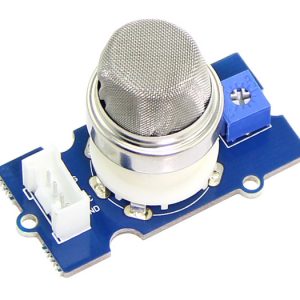
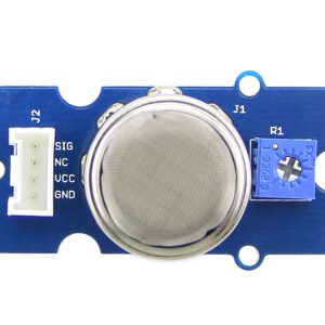
Grove – Gas Sensor(MQ5) 氣體感測器 Seeed
Grove氣體感測器(MQ5)模組可用於氣體洩漏檢測(在家庭和工業中)。可檢測液化石油氣,天然氣,城鎮煤氣等。基於其快速響應時間,測量可以盡快進行。且其靈敏度也可以通過電位器來進行調節。
NT$276NT$220 未稅 -
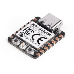
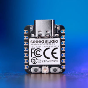
Seeed XIAO ESP32C5 開發板:雙頻 Wi-Fi 6 + BT 5.0 + Matter 支援
全新 XIAO ESP32-C5 採 RISC-V 核心,是 XIAO 系列首款支援 2.4/5GHz 雙頻 Wi-Fi 6 的開發板。整合 BLE 5、Zigbee 與 Thread,完全相容 Matter 協定。具備極低功耗深度睡眠模式(15µA)與板載電池管理,適合物聯網網關與智慧家居應用。
NT$381NT$340 未稅 -
Grove – Gas Sensor(MQ9) 瓦斯氣體 一氧化碳偵測感測器
Grove – Gas Sensor (MQ9) 瓦斯氣體偵測感測器模組,在家庭和工業上可以針對特定瓦斯氣體洩漏進行檢測且十分有用。對一氧化碳、甲烷、液化氣的靈敏度高,可檢測多種含一氧化碳及可燃性的氣體,是一款適合多種應用的低成本氣體感測器。
NT$300NT$280 未稅 -
XIAO Vision AI Camera 支援 Home Assistant 與無程式碼 AI 部署的智慧視覺方案
搭載 Himax WiseEye2 HX6538 與 Arm Ethos-U55 NPU,Grove Vision AI V2 套件支援無程式碼 AI 模型部署。透過 XIAO ESP32-C3 實現 Wi-Fi 連網,能與 Home Assistant 完美整合,打造本地端的 AI 自動化智慧監控系統。
NT$1,143NT$1,000 未稅 -
Seeed Grove 數位光敏感測器 (TSL2561) I2C 介面 寬量程 40,000 LUX 支援 Arduino & 樹莓派
Grove – Digital Light Sensor 數位型光敏感測器 是基於I2C 光度- 數位 轉換器, TSL2561 將光強度轉換為數位訊號。不同於傳統的類比式光感測器,數位光敏模組的特點是由於其雙光敏二極管,可選擇的光譜範圍:紅外線和全光譜。
NT$320NT$220 未稅 -
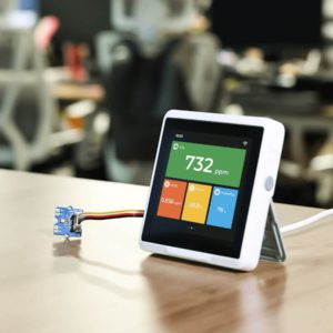
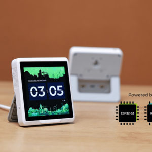
Seeed SenseCAP Indicator 開源物聯網觸控螢幕開發平台 (ESP32-S3 + RP2040) D1S版本
Seeed Studio SenseCAP Indicator 是一款 3.95 吋開源物聯網觸控螢幕開發平台。搭載 ESP32-S3 與 RP2040 雙 MCU,支援 Wi-Fi、藍牙及 LoRa 通訊,內建 CO2 與 tVOC 感測器,適合快速開發智慧家庭 Matter 節點與資料儀表板。
NT$2,200NT$1,800 未稅 -
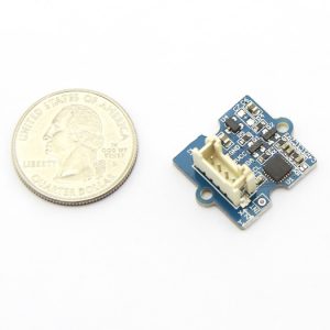
Grove – 3-Axis Digital Gyro 三軸陀螺儀感測器 (I2C) 搭載 ITG-3200 seeed原廠
想為您的 Arduino 專案加入精準的角速度偵測?Grove 三軸數位陀螺儀搭載業界領先的 ITG-3200 晶片,提供16位元高精度輸出,非常適合遊戲、3D滑鼠等體感應用。透過 Grove I2C 介面即可輕鬆連接。
NT$952NT$620 未稅 -
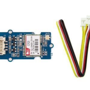
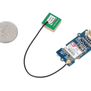
Seeed Studio Grove – GPS 定位模組 (u-blox 5 引擎 / UART 串口 / 高靈敏度) 適用 Arduino 與 Raspberry Pi
專為 Arduino 與 Raspberry Pi 開發者設計的 Grove – GPS 模組,採用標準 Grove 接口,無需繁雜跳線即可透過 UART 串口 讀取數據。搭載高效能 u-blox 5 定位引擎,具備 50 通道接收能力與 -160dBm 超高靈敏度,首次定位時間 (TTFF) 小於 1 秒。支援 NMEA 及 u-blox 6 協議,體積小巧且功耗低,適用於製作手持導航裝置與資產追蹤器。
NT$857NT$680 未稅