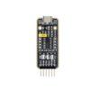

CANBed-Arduino CAN-BUS 套件 (帶有CAN-BUS的ATmega32U開發板)
NT$857 NT$800 未稅
CANBed-Arduino CAN-BUS 開發套件,搭載ATmega32U4晶片和MCP2515、MCP2551 CAN-BUS控制器和收發器,在單板上實現CAN-BUS通訊協議,無需其他MCU控制,本身就是一塊CAN-BUS開發板!
尚有庫存
- 商品說明
商品說明
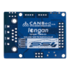
CANBed-Arduino CAN-BUS 開發套件 產品介紹
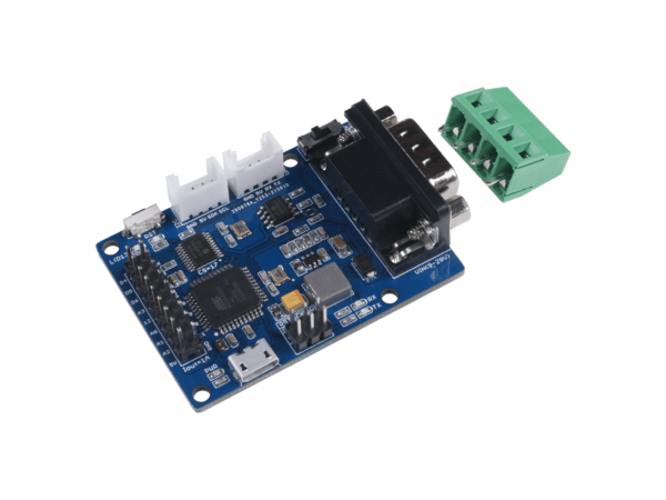
CANBed – Arduino CAN-BUS 開發套件內嵌了 ATmega32U4 晶片,這意味著您不需要在另一個 Arduino 板上添加其他跳線,它是一塊Arduino開發板本身加上 MCP2515 CAN 總線控制器和 MCP2551 CAN 總線收發器!CAN-BUS是一種通用協議,因其傳輸距離遠、通信速度中等、可靠性高而在工業中得到廣泛應用。現在你可以通過這個小小的開發板實現一個 CAN-BUS 項目。由於板載ATmega32U4芯片,該板的管腳資源豐富。事實上,板上基於核心芯片設置的引腳有18個,包括數字引腳、模擬引腳、UART和I2C接口。此外,該CANBed採用帶SPI接口的MCP2515 CAN總線控制器和MCP2551來實現CAN-Bus能力。還有兩種CAN總線接口可滿足各種需求,即sub-D9連接器和接線端子接口。它們將滿足您在連接方法中的所有需求。這款 CAN-Bus 開發板與 Arduino IDE 完美相容。借助 Arduino CAN-Bus 庫,您將為 CAN 項目節省大量時間。
特徵
- 板上帶有 Arduino Leonardo 引導加載程序的 ATmega32U4
- MCP2515 CAN 總線控制器和 MCP2551 CAN 總線收發器
- 在 sub-D 連接器上可選擇 OBD-II 和 CAN 標準引腳
- 相容於Arduino IDE
規格
| Parameter | Value |
|---|---|
| MCU | ATmega32U4(with Arduino Leonardo bootloader) |
| Clock Speed | 16MHz |
| Flash Memory | 32KB |
| SRAM | 2.5KB |
| EEPROM | 1KB |
| Operate Voltage(CAN-BUS) | 9-28V |
| Operate Voltage (MicoUSB) | 5V |
| Input Interface | sub-D |
應用
- 破解和升級你的車
- 車輛動態控制系統
- 姿態和軌道控制系統
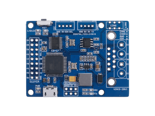
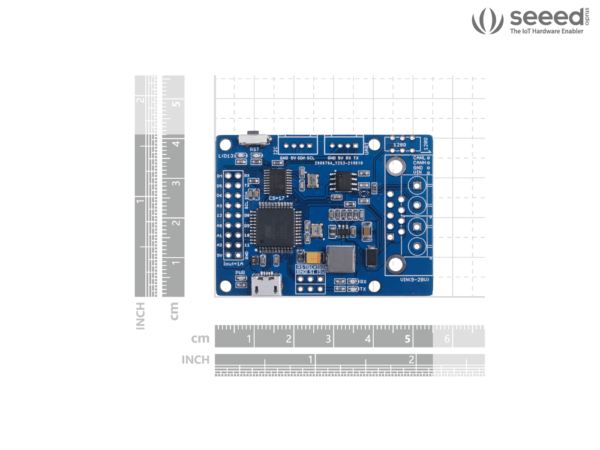
硬件概述

-
- 9×2 IO 引腳輸出:Atmega32U4 的 IO 列在這裡
- ATmega32U4:整個模塊的主控主要用於在TF卡上存儲數據或通過C型線將數據傳輸到電腦上。 由於它是Arduino相容的,你可以用它來實現一些簡單的控制,比如當速度超過一定值時觸發蜂鳴器報警。
A:重置按鈕:重置板載 Atmega 晶片。 - 用於編程的Micro USB連接器
- ICSP Header 用於上傳引導加載程序
- CAN RX/TX指示燈
- sub-D連接器或CAN總線終端
D-Sub CANbus 引腳輸出 - CAN總線120Ω終端電阻開關
- 用於UART的Grove連接器
- I2C 的 Grove 連接器
pin# Signal names Signal Description 1 Reserved Upgrade Path 2 CAN_L Dominant Low 3 CAN_GND Ground 4 Reserved Upgrade Path 5 CAN_SHLD Shield, Optional 6 GND Ground, Optional 7 CAN_H Dominant High 8 Reserved Upgrade Path 9 CAN_V+ Power, Optional 
如果你在 CAN 總線的末端使用這個端子,你需要在兩個焊盤之間焊接一個 120Ω 的電阻器,如果沒有就不需理會。
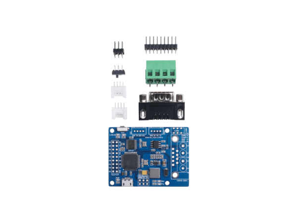
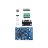
出貨清單
- CANBed PCBA (裸板,端子接頭需自焊)
- sub-D connector
- 4PIN Terminal
- 4PIN 2.0 Connector x 2
- 9×2 2.54 Header x 1
- 3×2 2.54 Header x 1
Documents
相關商品
-
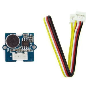
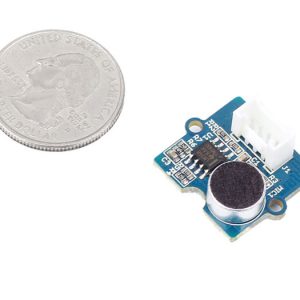
Grove-Sound Sensor 聲音感測器
Grove – Sound Sensor 聲音感測器 模組是一個麥克風元件。基於功率放大器LM386 電容式麥克風,它可以用於檢測偵測環境中的聲音強度。而偵測到的資料輸出的值可以由電位進行調整。
NT$238NT$180 未稅 -
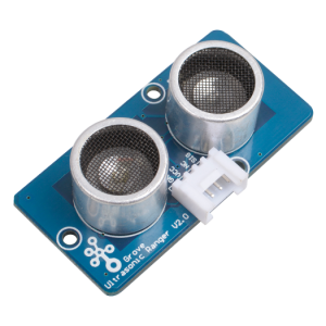
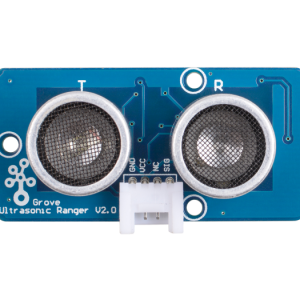
Grove – Ultrasonic Ranger 超音波測距模組 距離探測傳感器 seeed
Grove – Ultrasonic Sensor是一個非接觸式的距離探測模組。他的工作頻率在42KHz,適合用於中距離或近距離的探測。該模組具有超聲波發射器和超聲波接收器,因此您可以將其視為超聲波收發器。熟悉聲納,當發射器產生的40KHz超聲波遇到物體時,聲波將被發射回去,接收器可以接收反射的超聲波。
NT$190NT$140 未稅 -
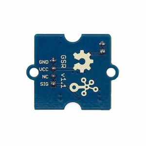
Grove – GSR Sensor 測謊器 皮膚電阻感測器 流汗感測器
GSR通過測量皮膚電流反應來測量皮膚電導率。強烈的情緒會刺激你的交感神經系統,導致汗腺分泌更多的汗水.Grove – GSR允許您通過簡單地將兩個電極連接到兩個手指來發現這種強烈的情緒,它能夠製作與情感有關的項目(如睡眠質量監視器),是一個很有趣的裝備。
NT$433NT$320 未稅 -
Grove – Digital Light Sensor 數位型光敏感測器 偵測光亮強度感測器
Grove – Digital Light Sensor 數位型光敏感測器 是基於I2C 光度- 數位 轉換器, TSL2561 將光強度轉換為數位信號。不同於傳統的模擬式光傳感器,數位光敏模組的特點是由於其雙光敏二極管,可選擇的光譜範圍:紅外線和全光譜。您可以在三種探測模式之間切換,把你的讀數。他們是紅外模式,全方位和人類可見模式。當人類可見模式下運行,該傳感器會給你的讀數只是接近你的眼睛感受。
NT$320NT$260 未稅 -
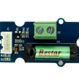
Grove – Dry-Reed Relay 磁簧管開關模組 干簧管繼電器模組 乾式磁簧繼電器
乾式磁簧繼電器的應用, 有如繼電器。支援 Arduino 與 Raspberry Pi 。
-
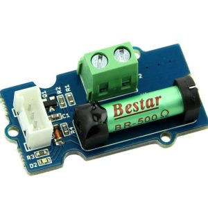
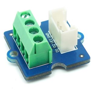
Grove – Screw Terminal 4P 螺絲端子座 額定功率可達 125V@6A seeed
Grove – Screw Terminal 4P 螺絲端子座有四個 3.5mm 端口座可達125V @ 6A。終端可以接受30〜20AWG線。這是最常見的螺距螺紋端子。Grove – Screw Terminal 有四個端口,包括GND,VCC和另外兩個未限定端口。
NT$100NT$80 未稅 -
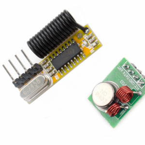
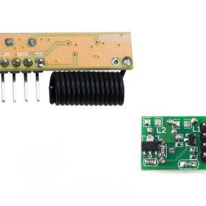
Grove – 433Mhz RF link kit RF 無線接收發射傳輸模組
該模組由發射器和接收器組成,廣泛用於遙控。
- 頻率:433Mhz。
- 接收器數據輸出:高 – 1/2 Vcc,低 – 0.7v
- Transmitor輸入電壓:3-12V(高電壓=更多發射功率)
- 發射範圍(工作在5V):室內40米,露天100米
NT$276NT$160 未稅 -
Grove – UV Sensor UV 紫外線感測器 seeed原廠
感測器用於檢測入射紫外線(UV)輻射的強度。這種形式的電磁輻射具有比可見輻射更短的波長。它基於感測器GUVA-S12D。它具有200nm-400nm的寬光譜範圍。模塊將輸出隨紫外線強度的變化而變化的電信號。UV感測器用於確定在實驗室或環境設置中暴露於紫外線輻射。
NT$457NT$300 未稅 -
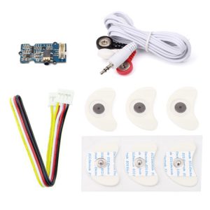
Grove – EMG Detector 肌電圖 檢測儀 肌肉信號/感測器 肌電檢測器
傳感器採集小肌肉信號然後進行第2次放大和濾波,輸出信號可以被Arduino識別。
NT$1,486NT$1,320 未稅 -
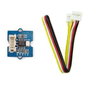
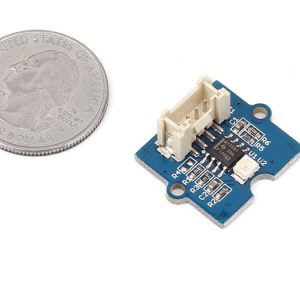
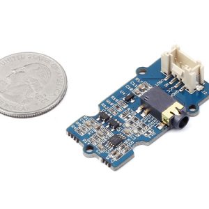
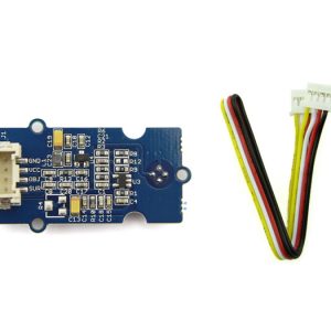
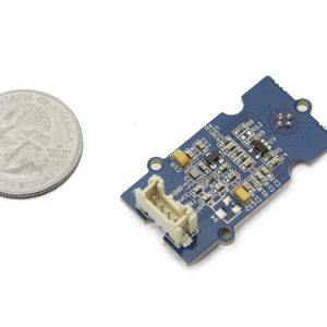
Grove-Infrared Temperature Sensor 紅外線溫度感測器模組
Grove 紅外線溫度感測器是一種非接觸式溫度測量模組,溫度感測器具有545μm的和抹黑表面活性直徑以吸收入射的熱紅外輻射浮動微膜組成的熱電偶串聯116個元素。紅外溫度感測器通過接收物體發出的紅外線來測量其溫度,輸出電壓為0~1.1V。
NT$457NT$380 未稅