
Arduino Motor Shield Rev3 電機驅動板 原廠公司貨 義大利製
NT$1,200 NT$1,000 未稅
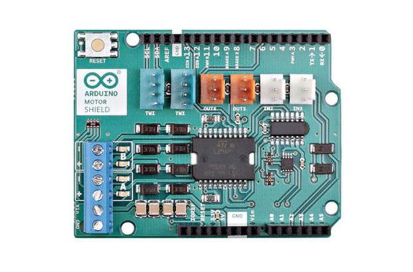
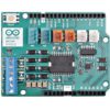
Arduino Motor Shield 是一塊Arduino電機驅動板,基於L298雙橋驅動晶片,可用於驅動感性負載(例如繼電器、螺線管、直流電機和步進電機等)。驅動板擁有兩路電機輸出,你可以用它來同時驅動2個直流電機,並單獨控制每個電機的轉速和方向。您還可以測量各個電機的吸收電流。擴展板相容TinkerKit,可以通過將TinkerKit模組插到電路板上來快速創建專案。
尚有庫存
- 詳情
商品說明
Arduino Motor Shield 是一塊Arduino電機驅動板,基於L298雙橋驅動晶片,可用於驅動感性負載(例如繼電器、螺線管、直流電機和步進電機等)。驅動板擁有兩路電機輸出,你可以用它來同時驅動2個直流電機,並單獨控制每個電機的轉速和方向。您還可以測量各個電機的吸收電流。擴展板相容TinkerKit,可以通過將TinkerKit模組插到電路板上來快速創建專案。
Arduino Motor Shield Rev3 技術規格
- 工作電壓:5V ~ 12V
- 電機控制器:L298P,驅動2個DC電機或1個步進電機
- 最大電流:每條通道2A或者最高4A(由外部電源供電)
- 電流感應:1.65 V/A
- 自由運轉停止和刹車功能
電源
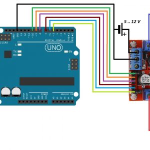
Arduino 馬達擴充板必須僅由外部電源供電。因為安裝在擴充板上的 L298 IC 有兩個獨立的電源連接,一個用於邏輯電路,一個用於馬達電源驅動器。所需的馬達電流通常超過 USB 的最大額定電流。
外部(非 USB)電源可以來自交流電轉直流轉接器(壁式電源轉接器)或電池。連接轉接器的方式是將 2.1 毫米中心正極插頭插入 Arduino 板安裝馬達屏蔽的電源插孔,或將連接電源的電線連接到 Vin 和 GND 螺絲端子,注意極性。
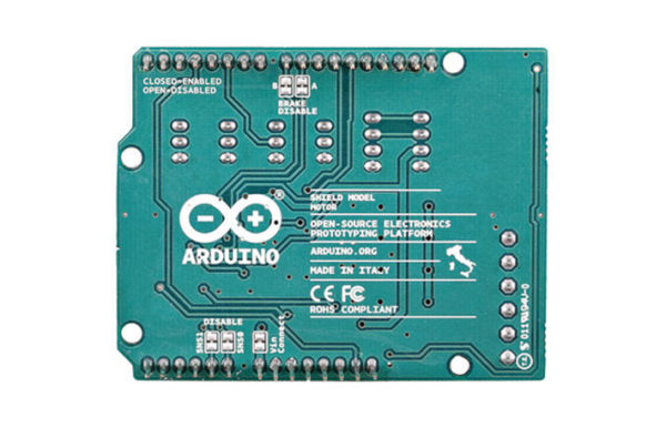
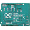
為避免損壞安裝擴充板的 Arduino 開發板,我們建議使用 7 至 12V 之間的外部電源。如果您的馬達需要超過 9V 的電壓,我們建議您將擴充板的電源線與安裝擴充板的 Arduino 開發板的電源線分開。這可以透過切斷 位於擴充板背面的「Vin Connect」跳線來實現。螺絲端子處的 Vin 電壓絕對上限為 18V。
電源引腳如下:
- 螺絲接線端子上的 Vin 是連接到屏蔽層的馬達的輸入電壓。連接到此引腳的外部電源也為安裝此板的 Arduino 板供電。剪斷 「Vin Connect」 跳線,即可將此接腳用作馬達的專用電源線。
- GND 螺絲接線端子上的接地。
屏蔽層每個頻道可提供 2 安培電流,總共最多可提供 4 安培電流。
輸入和輸出
此擴充板有兩個獨立的通道,分別稱為 A 和 B,每個通道使用 4 個 Arduino 引腳來驅動或感應馬達。此擴充板上總共使用了 8 個引腳。您可以單獨使用每個通道來驅動兩個直流電機,也可以將它們組合起來驅動一個雙極步進電機。擴充板的接腳(按通道劃分)如下表所示:
- 功能與引腳對應
- 方向
- 每聲道 A 腳數:D12
- 每聲道 B 腳數:D13
- 脈寬調製
- 每聲道 A 腳數:D3
- 每聲道 B 腳數:D11
- 煞車
- 每聲道 A 腳數:D9
- 每聲道 B 腳數:D8
- 電流感應
- 每聲道 A 腳數:A0
- 每聲道 B 腳數:A1
- 方向
如果您不需要煞車和電流感應功能,並且您的應用需要更多引腳,您可以透過切斷屏蔽背面相應的跳線來停用此功能。
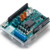
屏蔽上的附加插座說明如下:
螺絲端子 用於連接馬達及其電源。
2 個 TinkerKit 連接器 用於兩個類比輸入(白色),連接到 A2 和 A3。
2 個 TinkerKit 連接器 用於兩個 Aanlog 輸出(中間為橘色),連接到引腳 D5 和 D6 上的 PWM 輸出。
2 個 用於 TWI 介面的TinkerKit 連接器 (白色,4 針),一個用於輸入,另一個用於輸出。
馬達連接
有刷直流馬達。您可以將每根馬達的兩條電線分別連接到 A 通道和 B 通道的 (+) 和 (-) 螺絲端子上,從而驅動兩台有刷直流馬達。這樣,您可以透過將 DIR A 和 DIR B 引腳設定為高電平或低電平來控制馬達的方向,並透過改變 PWM A 和 PWM B 的 佔空比值來控制馬達的速度。 如果將Brake A 和 Brake B 引腳設定為高電平,則會有效地煞車直流電機,而不是透過切斷電源讓馬達減速。您可以透過讀取 SNS0 和 SNS1 引腳的讀數來測量流經直流馬達的電流。每個通道上都會有一個與測得電流成比例的電壓,可以透過類比輸入 A0 和 A1 上的 analogRead() 函數將其讀取為普通的類比輸入。為了方便起見,當通道輸出最大電流(即 2A)時,電壓已校準為 3.3V。
物理特性
馬達屏蔽 PCB 的最大長度和寬度分別為 2.7 英吋和 2.1 英吋。四個螺絲孔可用於將電路板固定在表面或外殼上。請注意,數位引腳 7 和 8 之間的距離為 160 mil(0.16 英吋),而不是其他引腳間距 100 mil 的偶數倍。
Arduino Motor Shield Rev3 文件檔案
Arduino Motor Shield Rev3 技術補充(英文)
以下為原廠英文技術說明,提供進階使用者參考。
The Arduino Motor Shield is based on the L298 (datasheet), which is a dual full-bridge driver designed to drive inductive loads such as relays, solenoids, DC and stepping motors. It lets you drive two DC motors with your Arduino board, controlling the speed and direction of each one independently. You can also measure the motor current absorption of each motor, among other features. The shield is TinkerKit compatible, which means you can quickly create projects by plugging TinkerKit modules to the board.
- Operating Voltage: 5V to 12V
- Motor controller: L298P, Drives 2 DC motors or 1 stepper motor
- Max current: 2A per channel or 4A max (with external power supply)
- Current sensing: 1.65V/A
Power
The Arduino Motor Shield must be powered only by an external power supply. Because the L298 IC mounted on the shield has two separate power connections, one for the logic and one for the motor supply driver. The required motor current often exceeds the maximum USB current rating.
External (non-USB) power can come either from an AC-to-DC adapter (wall-wart) or battery. The adapter can be connected by plugging a 2.1mm center-positive plug into the Arduino’s board power jack on which the motor shield is mounted or by connecting the wires that lead the power supply to the Vin and GND screw terminals, taking care to respect the polarities.
To avoid possible damage to the Arduino board on which the shield is mounted, we reccomend using an external power supply that provides a voltage between 7 and 12V. If your motor require more than 9V we recommend that you separate the power lines of the shield and the Arduino board on which the shield is mounted. This is possible by cutting the “Vin Connect” jumper placed on the back side of the shield. The absolute limit for the Vin at the screw terminals is 18V.
The power pins are as follows:
- Vin on the screw terminal block, is the input voltage to the motor connected to the shield. An external power supply connected to this pin also provide power to the Arduino board on which is mounted. By cutting the “Vin Connect” jumper you make this a dedicated power line for the motor.
- GND Ground on the screw terminal block.
The shield can supply 2 amperes per channel, for a total of 4 amperes maximum.
Input and Output
This shield has two separate channels, called A and B, that each use 4 of the Arduino pins to drive or sense the motor. In total there are 8 pins in use on this shield. You can use each channel separately to drive two DC motors or combine them to drive one bipolar stepper motor. The shield’s pins, divided by channel are shown in the table below:
- Function and Pin Mapping
- Direction
- Pins per Ch. A: D12
- Pins per Ch. B: D13
- PWM
- Pins per Ch. A: D3
- Pins per Ch. B: D11
- Brake
- Pins per Ch. A: D9
- Pins per Ch. B: D8
- Current Sensing
- Pins per Ch. A: A0
- Pins per Ch. B: A1
- Direction
If you don’t need the Brake and the Current Sensing and you also need more pins for your application you can disable this features by cutting the respective jumpers on the back side of the shield.
The additional sockets on the shield are described as follow:
Screw terminal to connect the motors and their power supply.
2 TinkerKit connectors for two Analog Inputs (in white), connected to A2 and A3.
2 TinkerKit connectors for two Aanlog Outputs (in orange in the middle), connected to PWM outputs on pins D5 and D6.
2 TinkerKit connectors for the TWI interface (in white with 4 pins), one for input and the other one for output.
Motors Connection
Brushed DC motor. You can drive two Brushed DC motors by connecting the two wires of each one in the (+) and (-) screw terminals for each channel A and B. In this way you can control its direction by setting HIGH or LOW the DIR A and DIR B pins, you can control the speed by varying the PWM A and PWM B duty cycle values. The Brake A and Brake B pins, if set HIGH, will effectively brake the DC motors rather than let them slow down by cutting the power. You can measure the current going through the DC motor by reading the SNS0 and SNS1 pins. On each channel will be a voltage proportional to the measured current, which can be read as a normal analog input, through the function analogRead() on the analog input A0 and A1. For your convenience it is calibrated to be 3.3V when the channel is delivering its maximum possible current, that is 2A.
Physical Characteristics
The maximum length and width of the Motor Shield PCB are 2.7 and 2.1 inches respectively. Four screw holes allow the board to be attached to a surface or case. Note that the distance between digital pins 7 and 8 is 160 mil (0.16″), not an even multiple of the 100 mil spacing of the other pins.
相關商品
-
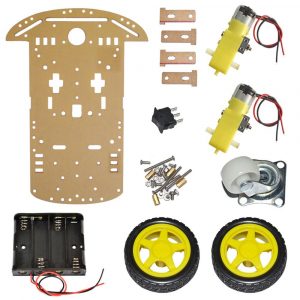
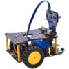
兩驅 2WD 智慧小車 自走車 機器人 底盤開發套件組
Arduino ,樹莓派 適用 兩驅 2WD 智慧小車 / 自走車/ 機器人 底盤開發套件組
小車都以散件形式發貨(便於運輸),附有3D安裝圖紙,拿到手後按照圖紙只要十分鐘就可以安裝完成,非常簡單,您可以利用本開發套件組結合 Arduino 或者樹莓派或其他單片機開發出您專屬的智慧小車。本套件全新升級不加價,底盤加大16CM*22CM,長寬比普通三輪小車分別加大2CM,巡線擺動更穩定,TT電機支架加厚2MM,比原來老款車型堅固、載重能力安裝方便,結構合理,結實耐用。
NT$457NT$300 未稅 -
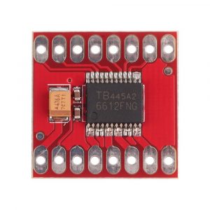
TB6612FNG Dual Motor Driver 超小設計雙馬達驅動板 CJMCU
TB6612FNG電機驅動模組小體積高性能超L298N 自平衡小車3PI配套. 該模組相對於傳統的L298N效率上提高很多,體積上也大幅度減少,在額定範圍內,晶片基本不發熱,當然也就顯得更加嬌貴,所以我們建議有一定動手能力的朋友使用,接線的時候務必細心細心再細心,注意正負極性。
NT$214NT$160 未稅 -
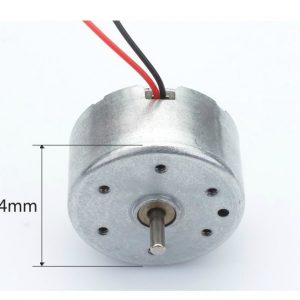
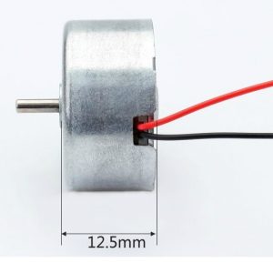
小型扁圓形直流馬達 5V
小型扁圓形直流馬達 5V,軸的直徑:2mm。
NT$48NT$40 未稅 -
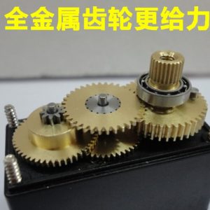
MG995 金屬銅齒輪 55G 舵機 180度
應用於雙足機器人機械手、遙控車、遙控船、汽油機 專用舵機,機器人製作舵機基地,全金屬齒輪,非常耐磨, 13 公斤扭力,非常給力。
NT$190NT$160 未稅 -
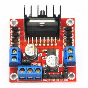
L298N DC 直流電機驅動板 步進電機驅動器 帶散熱片
L298N DC 馬達驅動模組, 可控制 2個DC馬達, 或1個2相4線步進馬達, 適用 Arduino /51/AVR/AVR/ARM 各種微控制器。現在市面上出現仿本公司模產組品,本公司的L298晶片是全新正品晶片,貼片鋁電解是採用2個35V 220UF高電壓高容量電容,而仿的模組採用的是翻新2手晶片, 35V 100UF和10V 100UF低電壓低容量電容.請大家購買時認清.以免上當受騙,把電路板全燒掉.
NT$100NT$60 未稅 -
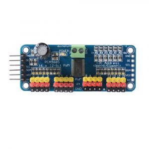
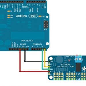
原廠 PCA9685 16路舵機控制擴展板 16路12-bit PWM控制板
NT$280 未稅PCA9685是一款16路舵機控制擴展板,此驅動板最多可級聯62個驅動板,總共可以驅動992個舵機,實現多自由度機械臂,六足機器人,多軸控制等應用。只要你的主控晶片具備了I2C通信,就能夠讓主控晶片和PCA9685通信,實現多個 舵機的同時控制了。
-
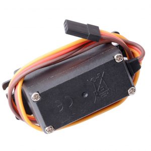
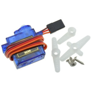
servo 9g SG90 舵機 9克伺服機 180度 伺服馬達 1.5Kg扭力 品質穩定
全新開發 SG90 舵機伺服器,採用全新高強度工程材料注塑成形,保證了色澤美觀及運作穩定性。重量輕~準度佳。
適用遙控飛機/遙控直升機/遙控車/機器人/自動控制實驗/自走車 …等等多種場合,貼心小提示: 伺服器工作電壓為直流電DC 4.8V~6.0V 哦!NT$95NT$60 未稅 -
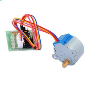
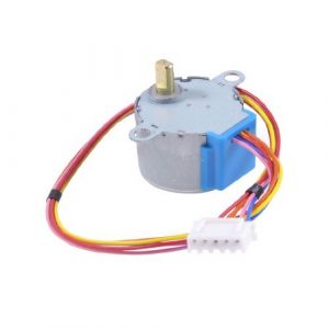
ULN2003 步進馬達 驅動模組 + 5V步進馬達(4相5線 28BYJ-48-5V)
使用 ULN2003 大功率達林頓晶片驅動步進電機,A、B、C、D 發光二極體指示四相步進電機工作時的狀態,配有步進電機的標準介面,使用時可直接拔插。
- 板載ULN2003A馬達驅動晶片
- 晶片所有管腳已經引出,方便連接使用
- 插針5-12V供電
- 板載4路信號指示燈
- 板載XH-5P插座,可以直接連接28BYJ-48型號的步進馬達
- PCB板子尺寸:40.5(mm)x21.3(mm)
NT$114NT$95 未稅 -
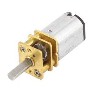
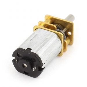
GA12-N20 微型金屬減速馬達 全金屬齒輪 體積小、扭力大、全金屬齒輪,耐用不易磨損
GA12-N20 微型金屬減速馬達全金屬齒輪 體積小、扭力大、全金屬齒輪,耐用不易磨損。可順逆/正反轉具有自鎖功能噪音小扭矩大. 電機精小,用處大,做用廣.是開發者的首選。GA12-N20 微型金屬減速馬達體積小,扭力大,電流小,減速比越大,電機運行越靜音。12 MM 直流減速馬達可用 PWM 控速。
NT$167NT$100 未稅 -
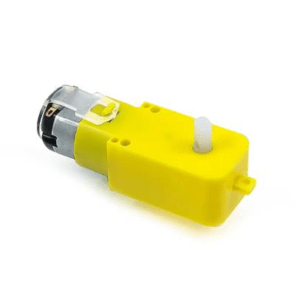
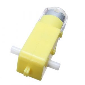
DC 3V-6V 塑膠 直流減速馬達 減速比1:48
NT$38 – NT$48 未稅直條減速馬達 1:48 減速比
- 強磁、帶抗干擾
- 電壓 空載電流 空載轉速
- 6V ≤200mA 200±10% rpm
- 3V ≤150mA 90±10% rpm
單軸、雙軸 兩種規格可供選擇