
LiPo Charger Booster 3.7V 鋰聚合電池升壓 5V1A 充電保護模組 SparkFun原廠
- 詳細資訊
商品說明
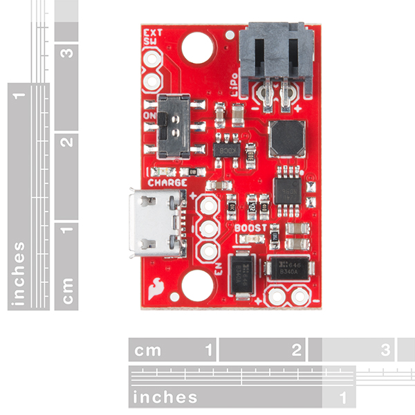
LiPo Charger Booster 3.7V 鋰聚合電池升壓 5V1A 充電保護模組
LiPo Charger Booster 使用 PAM2401 IC 的簡單升壓電路,並且包括保護二極管,以便您可以串聯運行多個電池,以增加額外的衝擊。當升壓電路運行時,該板可以吸入更多的電流,輸入電壓越低,使其在少量時間內提供強電荷是完美的。該電路是通過將MCP73831充電控制器IC饋送到LiPo端口和PAM2401升壓控制器的輸入來構建的。為電池,充電源和開關提供多種連接類型,以實現應用的靈活性,兩個LED可提供有關係統狀態的反饋。如果您的項目需要超過5V,SparkFun LiPo充電器/ Boosters也可以通過連接器連接起來,以獲得更大的電壓。
該電路通過將MCP73831充電控制器IC饋送到LiPo電池端口和PAM2401升壓控制器的輸入來構建。電源總是流向升壓電路,因此,如果需要,可以在充電期間提供使能引腳以使增壓器關閉。為電池,充電電源和開關提供多種連接類型,以實現應用的靈活性。
特徵
- 充電器,microUSB,500mA
- 增壓器,5V,1A輸出
- 我們的1,000mAh電池的外形尺寸
- 電池隔離開關,帶可選外部連接
- 啟用引腳分解
- 禁用電流小於10uA
- LED指示燈用於電源和充電
- 超潔淨輸出信號(高頻切換)
硬件概述
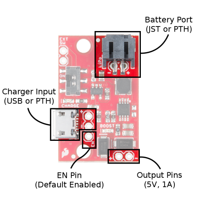
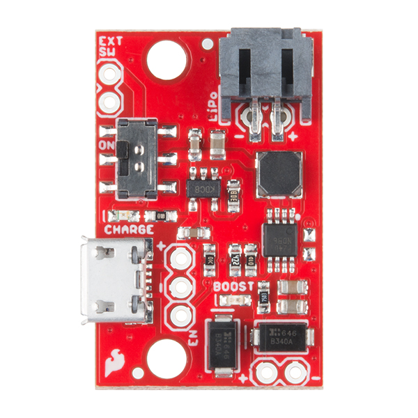
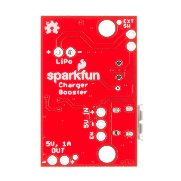
5V / 1A充電器/增壓器的充電器輸入,電池端口,使能引腳和輸出引腳。
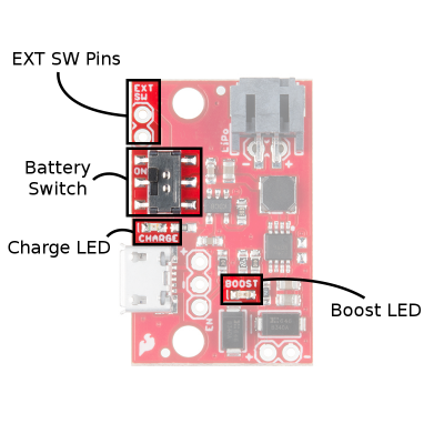
下圖顯示了表面貼裝電池開關和外部開關引腳的位置,以提供控制輸出的附加選項。包括兩個LED以提供有關係統狀態的反饋。
為5V / 1A充電器/增壓器提供開關選項和狀態指示燈。
功能
| 項目 | 描述 |
|---|---|
| 輸出引腳 | 得到5V,1A在這裡!’OUT’引腳用極性標記。 |
| 電池端口 | 在這裡插入LiPo電池通過JST連接器或直接焊接到連接器下方的PTH引腳。這些ins標有極性。 |
| 充電器輸入 | 供應5V,500mA這裡充電。您可以使用micro-B USB電纜或焊料直接連接到PTH引腳。這些“IN”引腳被標記為極性。 |
| 電池開關 | 車載開關是物理電池斷開。當處於ON位置時,電池連接到增壓器/充電器。當翻轉到OFF位置時,電池的正極引線與所有電子元件隔離,並且將繪製零電流。 |
| EXT SW針 | 它們平行於板載電池開關觸點。可以通過這些引腳連接更高電流的開關。如果您不斷吸取大電流或想要遠程電池斷開開關,請在此連接。 |
| EN引腳 | EN引腳默認使能。該引腳浮起來,可以連接到地,關掉輸出。如果您的負載電路不能進入低功耗模式進行充電,這很有用。 |
| 充電LED | 當充電器IC正嘗試為電池充電時,充電指示燈指示藍色。當電池充滿電時,它將關閉。 注意:如果電池正在充電時正在繪製電流,充電器可能會認為電池電量不夠充足,並繼續採購電流。 |
| 升壓LED | 當輸出引腳上存在電壓時,該指示燈顯示紅色。 |
充電狀態LED
板載藍色CHARGE LED可用於顯示電池的充電狀態。以下是根據充電IC狀態的其他狀態指示表。
| 充電狀態 | LED狀態 |
| 沒有電池 | 浮動(應關閉,但可能會閃爍) |
| 關掉 | 浮動(應關閉,但可能會閃爍) |
| 充電 | 上 |
| 充電完成 | 關閉 |
Documents
=========================================================
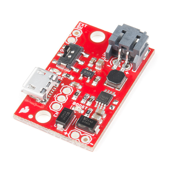
SparkFun LiPo Charger/Booster – 5V/1A
The SparkFun 5V/1A LiPo Charger/Booster is a no-nonsense circuit for generating one amp from a Lithium Polymer battery at 5V. This LiPo charger is a very economical choice that is equipped with a simple booster circuit utilizing the PAM2401 IC, and includes protection diodes so you can run multiple cells in series for an extra kick. While the booster circuit is in operation, this board can draw more current the lower the input voltage, making it perfect to deliver a strong charge in a small amount of time.
The circuit is constructed by feeding an MCP73831 charge controller IC to the LiPo port, and to the input of a PAM2401 boost controller. Multiple connection types are provided for the battery, charge source and switch to allow flexibility of application, and two LEDs provide feedback on system status. If you need more than 5V out of your project, the SparkFun LiPo Charger/Boosters can also be daisy-chained together to get a bigger bang for your buck.
Note: This is not a direct replacement for the SparkFun Power Cell, as it uses a different IC. Also, this board does not possess any undervoltage or other battery protection features, so we do recommend that you use it only with batteries with a built-in protection circuit.
Features
- Charger, microUSB, 500mA
- Booster, 5V, 1A output
- Form factor for our 1,000mAh batteries
- Battery isolation switch with optional external connections
- Enable pin broken out
- Disabled current less than 10uA
- LED indicators for power and charge
- Super-clean output signal (high-frequency switching)
Hardware Overview
Parts of the Board
The circuit is constructed by feeding an MCP73831 charge controller IC to the LiPo battery port, and to the input of a PAM2401 boost controller. Power always flows to the boost circuit, so an enable pin is provided to allow the booster to be shut down during charging if desired. Multiple connection types are provided for the battery, charge source, and switch to allow flexibility of application.

The image below shows the location of the surface mount battery switch and external switch pins which are included to provide an additional option to control the output. Two LEDs are included to provide feedback on system status.

Functions
| Item | Description |
|---|---|
| Output Pins | Get 5V, 1A out here! The ‘OUT’ pins are labeled with polarity. |
| Battery Port | Insert a LiPo battery here through the JST connector or solder directly to the PTH pins underneath the connector. These ins are labeled with polarity. |
| Charger Input | Supply 5V, 500mA here to charge. You can use a micro-B USB cable or solder directly to the PTH pins. These ‘IN” pins are labeled with polarity. |
| Battery Switch | The on-board switch is a physical battery disconnect. When in the ON position, the battery is connected to the booster/charger. When flipped to the OFF position, the battery’s positive lead is isolated from all electronics, and zero current will be drawn. |
| EXT SW Pins | These run parallel to on-board battery switch contacts. A higher current switch can be connected through these pins. If you’re constantly drawing large currents or want a remote battery disconnect switch, connect it here. |
| EN Pin | The EN pin is enabled by default. This pin floats high and can be connected to ground to turn the output off. This is useful if your load circuit can’t be put into low power mode for charging. |
| Charge LED | The charge LED indicates blue when the charger IC is attempting to charge the battery. It will turn off when the battery is fully charged. Note: If current is being drawn while the battery is being charged, the charger may think the battery is never quite full and continue sourcing current. |
| Boost LED | This LED indicates red when voltage is present on the output pins. |
Charge Status LED
The on-board blue CHARGE LED can be used to get an indication of the charge status of your battery. Below is a table of other status indicators depending on the state of the charge IC.
| Charge State | LED status |
| No Battery | Floating (should be OFF, but may flicker) |
| Shutdown | Floating (should be OFF, but may flicker) |
| Charging | ON |
| Charge Complete | OFF |
Documents
- Schematic
- Eagle Files
- Hookup Guide
- Datasheets
- GitHub
相關商品
-
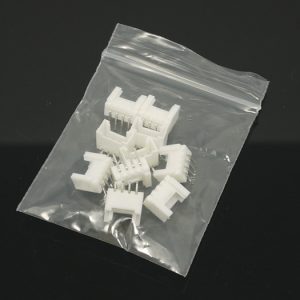
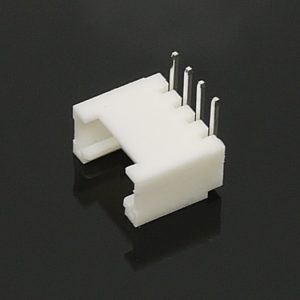
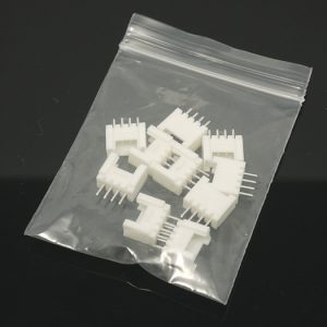
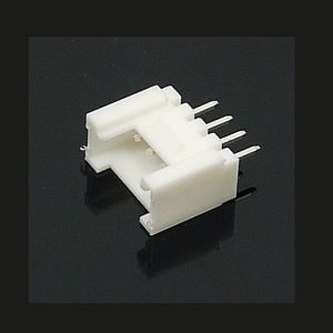
Grove – Universal 4 pin connector 通用4針90°端子頭 (10個一包) seeed
Grove – 通用4針連接器90°是用於Stem,Twigs和Grove電纜的白色4針彎曲連接器,引腳間距為2mm。每個包有10個連接器,用戶可以使用它們DIY。
NT$76NT$60 未稅 -
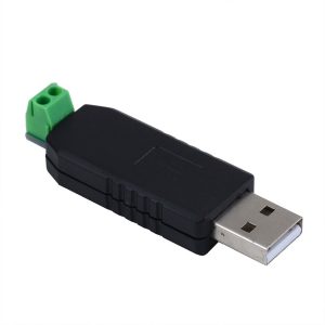
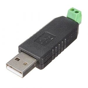
USB 轉 RS485 模組 二線 RS-485 模組 FT232晶片
USB 轉 RS485 模組:採用 FT232 晶片,支援二線 RS-485 通訊,具備 LED 指示燈。廣泛應用於機床 PLC、監控、門禁系統、工業自動化、儀器儀錶、停車場及考勤機等數據通訊與控制場景。
NT$80NT$60 未稅 -
特價出清 4.0 藍芽接收傳輸器 Bluetooth V4.0 USB介面 win7/win8 免驅動
4.0 藍牙接收傳輸器 是一款 USB 介面的藍牙 4.0 雙模適配器,適用於桌上型電腦和筆記型電腦。支援 XP、Vista、Win 7/8 等主流作業系統,傳輸速度理論上可達 3M/秒,接收距離最遠可達 20 米 (Class 2)。具備 一鍵配對 功能,可連接藍牙耳機、滑鼠、鍵盤、音響等設備,並支援 Wake-on-WLAN/Bluetooth 節能功能。
NT$80NT$40 未稅 -
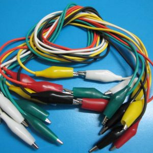
雙頭鱷魚夾測試線 (10條),50cm 維修實驗必備
【電子實驗必備】五色鱷魚夾測試線,每色兩條共10入,線長50cm。 適用於 Arduino、樹莓派、麵包板等各種電子專案,維修與教學的最佳工具。顏色分類清晰,方便辨識與使用,讓您的電路測試更有效率!
NT$124NT$60 未稅 -
Grove – Universal 4 pin connector 端子接頭 (10個一包) seeed
Grove – Universal 4 pin connector 是用於Stem,Twigs和Grove電纜的白色4針彎曲連接器,引腳間距為2mm。 每個包有10個連接器,用戶可以使用它們DIY。
NT$76NT$60 未稅 -
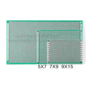
雙面洞洞板 (噴錫) – 5x7cm、7x9cm、9x15cm 三尺寸可選
NT$20 – NT$60 未稅【電子實驗必備】雙面噴錫洞洞板,厚度 1.6mm,提供 5x7cm、7x9cm、9x15cm 三種尺寸。 採用高品質玻璃纖維綠油板,孔距 2.54mm,孔徑 0.95mm。適合各種電子電路焊接與原型設計,DIY專案與教學實驗。
-
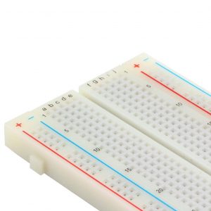
MB-102 麵包板 830孔 多功能實驗板 萬能洞洞板 彩條線路板 電路板
MB-102 優質麵包板 線路板 麵包板 實驗板 萬能板 165×55×10mm;一個端子條:630個插孔,兩個分配條:200個插孔,產品尺寸:5.6×16.5×0.85(cm),磷青銅鍍鎳彈簧夾,匹配跳線,線徑0.8mm,塑件:ABS,用途:實驗、測試。
NT$76NT$60 未稅 -
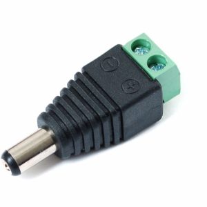
免焊接 DC 2.1mm 公頭 – 接線式電源轉接頭
NT$20 未稅【免焊接】DC 2.1mm 公頭轉接頭,支援 1V-38V 寬電壓輸入,最大電流 20A。 鎖螺絲設計,無需焊接,輕鬆連接 Arduino、9V 電池或 AA 電池盒。採用耐用材質,並標示正負極,是電子製作與互動媒體專案的便利工具。
-
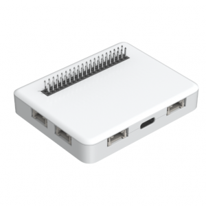
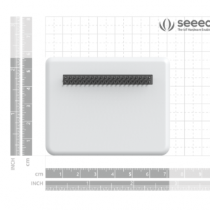
Wio Terminal Battery Chassis 鋰電池擴充盒 內置650mAH鋰電池 6個Grove接口
Wio鋰電池擴充盒是Wio開發板的必備擴展板,因為它為Wio終端提供了外部電源,以增強其便攜性和緊湊性。它具有650mAH可充電鋰聚合物電池,4個Grove模擬/數字端口,個Grove I2C端口和1個Grove UART端口,以及美觀的ABS防護外殼。Wio終端電池機箱的背面也有相同的Raspberry Pi 40引腳兼容GPIO,以提供更多附加組件!
NT$640NT$560 未稅 -
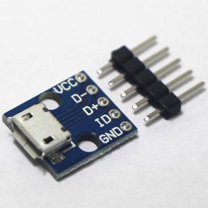
MicroUSB 接口座電源轉接模組
NT$40 未稅Micro USB 接口座電源轉接模組 USB 電源轉介面 麵包板 5V電源模組